ME218B: Smart Product Design Applications
Overview:
ME218B is the second course in Stanford's graduate level Mechatronics series. In this course, you learn about user I/O, timer systems, interrupts, signal conditioning, software design for embedded systems, state charts, sensors, actuators, noise, and power supplies. You also get to apply that knowledge through four labs and a team course project.
Labs:
MCU used for all labs: TI's Tiva Launchpad, an ARM Cortex M4F evaluation board,
Lab 1 (Individual): I programmed firmware to perform wave drive, full step, half step, and micro-stepping. The speed of steps was given by an analog input and change step directions when a button was pressed.
Lab 2 (Individual): I programmed firmware to enable PWM peripheral to control a DC motor and set up input capture for encoder to measure speed. DC motor was spun proportional to an analog value.
Lab 3 (Individual): This lab continued work from lab 3. The DC motor was driven via Drive-Break mode and closed loop speed control was performed with a periodic hardware timer.
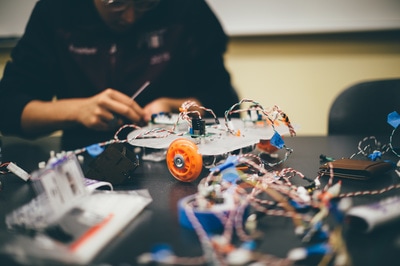
Lab 4 (Team): The object of this lab was to create a mobile platform that drove around, sensed an IR LED beacon, and received commands from a black box module via SPI. My responsibility of the labs was to write the firmware to initialize and communicate via SPI and post process the commands. A code sample of this initialization can be seen below.
Team Project:
Please see the link at the bottom of the page for even more information including electrical schematics, code, and pictures.
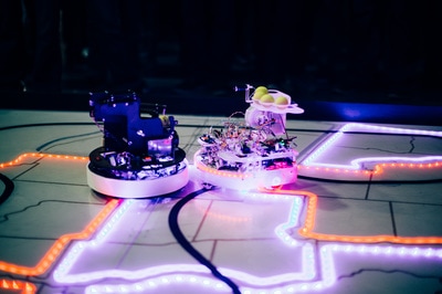
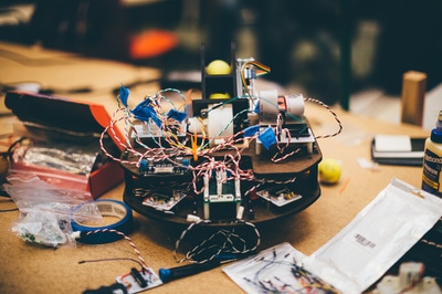
The goal of this project was to design and build a machine that autonomously navigated to play a game. For our project, I was responsible all the robot's sensors, signal conditioning, and the SPI/sensor firmware. The robot was controlled by TI's Tiva Launchpad, an ARM Cortex M4F evaluation board, and was powered by 2 NiCd batteries.
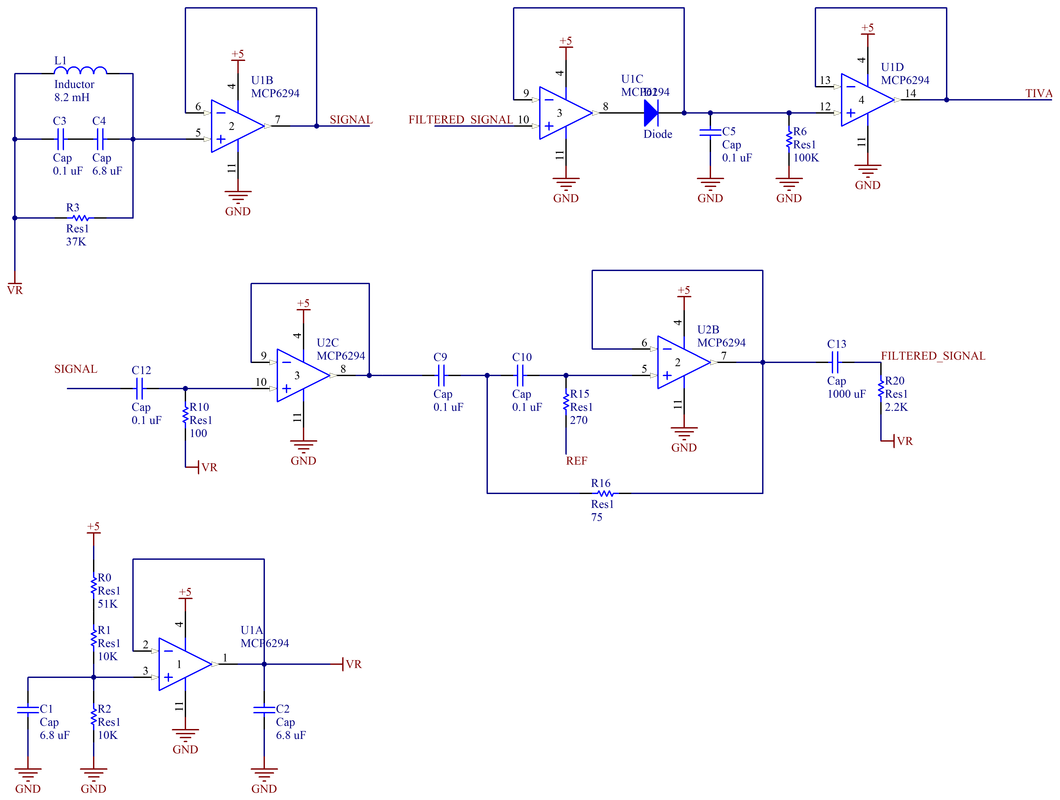
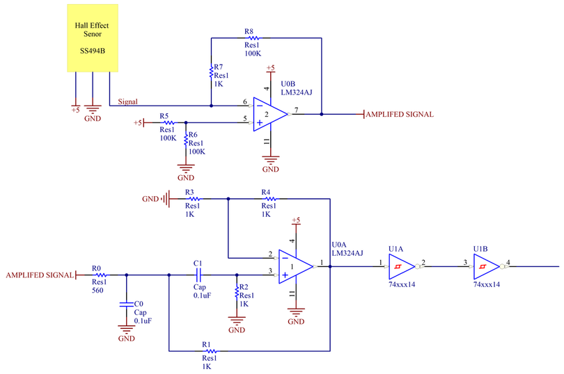
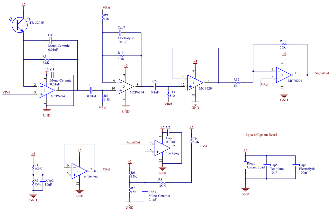
Our strategy for the game relied on sensing 3 things robustly: a wire carrying a 100mA current modulated at 20kHz for navigation, an oscillating magnetic field for capturing stations, and a long range IR receiver for aligning to beacons to shoot a ball. To sense the wire, I designed two tuned resonance circuit to pick up the oscillating current. The station's magnetic field was so large enough to overcome the small gain for low frequencies of the resonance circuit that a third order Butterworth filter was required to prevent capturing a station from affecting our navigation. The wire signal was then run through a peak detector give an analog value relating to how close the robot was to the line. To sense the station's oscillating magnetic field, a hall effect sensor was applied and conditioned so that the EMF from the motors did affect the signal. To do long range sensing, a photo transistor was amplified and filtered in stages to be able to detect IR from over 7 feet away. Schematics for these circuits can be found below.
Wire Sensing Circuit
Hall Effect Circuit
Infrared Light Detecting Circuit
